Data sheet
Wieland Coaxial Heat Exchangers
Condenser and Evaporator with optimum counter-flow layout

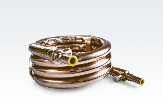
Wieland coaxial heat exchangers are used as condensers (WKC) or as evaporators (WKE). Depending on the performance they consist of one or more thermal optimized inner tubes and one outer tube. The counter-flow layout ensures an optimum heat exchange.
Calculate your coaxial heat exchanger directly online:
ThermalS
Coaxial Condensers WKC
Wieland Coaxial Condensers are normally used in applications which require high water temperatures in conjunction with the use of hot gaseous refrigerant. For a low-noise, non-vibration operation, dents are pressed into the jacket tube.
Coaxial Evaporators WKE
These Coaxial Heat Exchangers are the preferred choice in applications where water needs to be cooled significantly. At the same time they also offer reliable superheating of the suction vapour, which is supported by the counter-flow layout. A low-noise operation is achieved by spacer rings in the jacket tube.
| Model |
Number of inner tubes |
Installation dimensions [mm] |
Connection dimensions [mm] | Volume [l] | Weight appr. [kg] |
Classification PED 2014/68/EU |
|||||||
|---|---|---|---|---|---|---|---|---|---|---|---|---|---|
| Refri- gerant |
Coolant |
Refri- gerant |
Coolant |
||||||||||
| A | B | H | d1* | d2*/d3* | d** | a | h | ||||||
| WKC 10*** | 1 | 225 | 270 | 135 | 16 | 12.7 | 15.9 | 190 | 98 | 0.6 | 0.3 | 3.5 | sound engineering practice |
| WKC 15*** | 1 | 230 | 290 | 235 | 18 | 16.0 | 19.0 | 190 | 196 | 1.0 | 0.8 | 7.5 | sound engineering practice |
| WKC 20 | 1 | 350 | 360 | 220 | 22 | 21.7 | 25.5 | 300 | 172 | 1.8 | 1.75 | 10.5 | Category 1 Module A |
| WKC 45 | 4 | 520 | 530 | 225 | 35 | 28.0 | 31.9 | 445 | 152 | 3.7 | 2.9 | 21.0 | Category 1 Module A |
* Internal soldering ends
** External soldering ends
***Optional suitable for fluid group 1

Condensers WKC
1 Coolant outlet | e.g. heating water
2 Coolant inlet | e.g. heating water
3 Refrigerant outlet
4 Refrigerant inlet
| Model |
Number of inner tubes |
Installation dimensions [mm] |
Connection dimensions [mm] | Volume [l] | Weight appr. [kg] |
Classification PED 2014/68/EU |
|||||||
|---|---|---|---|---|---|---|---|---|---|---|---|---|---|
| Heating medium |
Refrigerant |
Heating medium |
Refri- gerant |
||||||||||
| A | B | H | d1* | in d2* |
out d3* |
a | h | ||||||
| WKE 10** | 1 | 330 | 325 | 130 | 16 | 13 | 13 | 290 | 94 | 0.8 | 0.4 | 4.1 | sound engineering practice |
| WKE 16** | 2 | 340 | 390 | 190 | 28 | 22 | 22 | 290 | 140 | 1.8 | 0.9 | 8.1 | sound engineering practice |
| WKE 24 | 3 | 435 | 465 | 175 | 28 | 18 | 18 | 380 | 122 | 2.4 | 1.3 | 11.1 | sound engineering practice |
| WKE 44 | 5 | 605 | 600 | 220 | 35 | 22 | 28 | 530 | 150 | 4.9 | 2.9 | 24.7 | Category 1 Module A |
* Internal soldering ends
For WKE 10 the fitting on the refrigerant side can be used as external soldering end d4 with ∅ 16 mm (e.g. for tube ∅ 18 x 1 mm).
**Optional suitable for fluid group 1

Evaporators WKE
1 Refrigerant outlet
2 Refrigerant inlet
3 Heating medium outlet
4 Heating medium inlet

Customized Design
Individual coaxial heat exchangers are available with customized series. Suitable for additional performance range and the use with natural refrigerants and operating pressures higher than 35 bar. An individual design can be fitted to your construction requirements.
Advantages
- High specific performance through optimized inner tubes
- Counter-flow
- Frost-proof
- Low fouling
- Long life
- Reversible operation possible
Applications
- Heat pumps for hot water
- Chillers
- Cascade heat exchangers in multistage refrigeration systems
- Temperature control units/climate chambers
- Air conditioning and heating in marine applications
Operating range
- Max. operating pressure:
35 bar (refrigerant side)
15 bar (fluid side) - Max. operating temperature:
- 50°C to + 150°C
(Exception: WKE 16: - 50°C to + 110°C)
Assembly instructions
Coaxial heat exchangers should preferably be operated in counter-flow operation. The inner tubes as well as the jacket tube and brazed T-fittings are made of Cu-DHP.
Condensers WKC are installed so that the liquefied refrigerant is free to drain away to the bottom. The hot gaseous refrigerant enters the jacket space at the top, whereas the cooling medium (e.g. water) enters the inner tube(s). Coaxial condensers are also installed standing on the windings (winding axis horizontal). If an application requires several condensers to be connected in parallel, then the tubing should be designed in such a way that each condenser can be supplied with even pressure on both the refrigerant side and the cooling medium side.
The routing of the hot-gas line should be installed avoiding any vibrations. This is normally achieved by installing vibration dampers (compensators). In order to avoid pulsating noises, we recommend installing a sound muffler between the compressor and the condenser. Please follow the manufacturer`s instructions when installing these components.
The installation of evaporators WKE preferably allows the refrigerant to enter through the bottom connection. If several evaporators of the same size are to be connected in parallel, then it must be ensured that each evaporator is supplied with even pressure both on the refrigerant side and on the heating medium side.
For an approximation of the refrigerant capacity of the overall system following proportions of the refrigerant side volume should be used as an approximation: WKC: 30%, WKE: 40%
Quality Assurance
Responsibility begins with a high standard of quality. As the first company for semi-finished products in Europe, we have been on the path to certified quality management since 1987.
Today, we have DIN EN ISO 9001:2015 certifications for all producing plants, and our testing laboratories in Ulm and Vöhringen are additionally accredited to DIN EN ISO/IEC 17025:2018.
Pressure Equipment Directive
Coaxial heat exchangers correspond with the Pressure Equipment Directive 2014/68/EU. They are normally classified in the categories mentioned in the overview and are manufactured and supplied in accordance with the measures designated for this purpose. Operating conditions which exceed these specifications are subject to special requirements which should be agreed separately for each individual case.

Your contact for heat exchangers
Wieland Thermal Solutions
Heat exchangers

